PACcubes and IBM Watson IoT Platform
1 The task
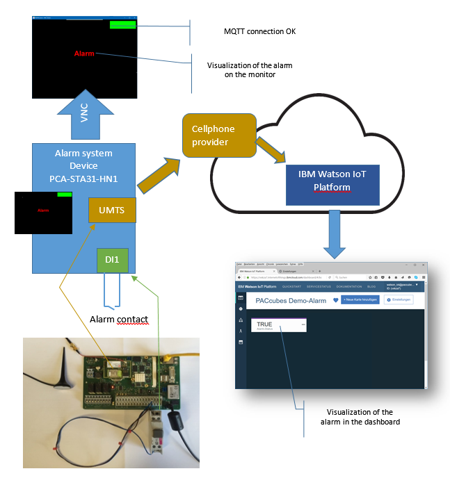
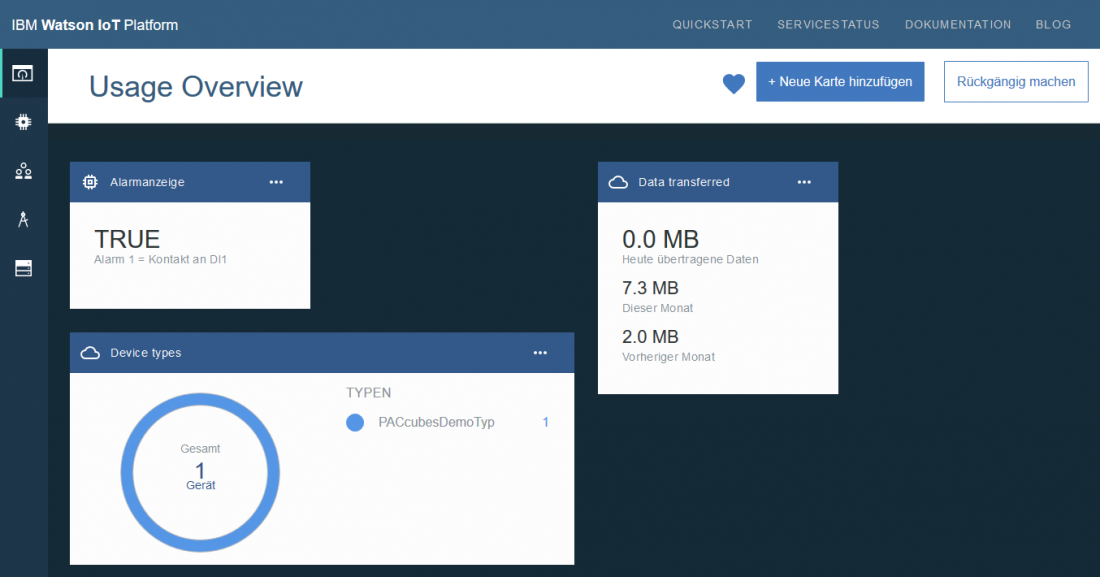
The controller PACcubes PCA-STA31-HN1 is connected to an n.o. contact at digital input 1. This n.o. contact will be used as alarm contact. As soon as the contact is closed, an alarm event should be sent to the IBM Watson IoT Platform. This event should then be visualized in the IBM Watson IoT Dashboard on a simple digital display (TRUE/FALSE).
The internet communication will be realized over an integrated UMTS radio module.
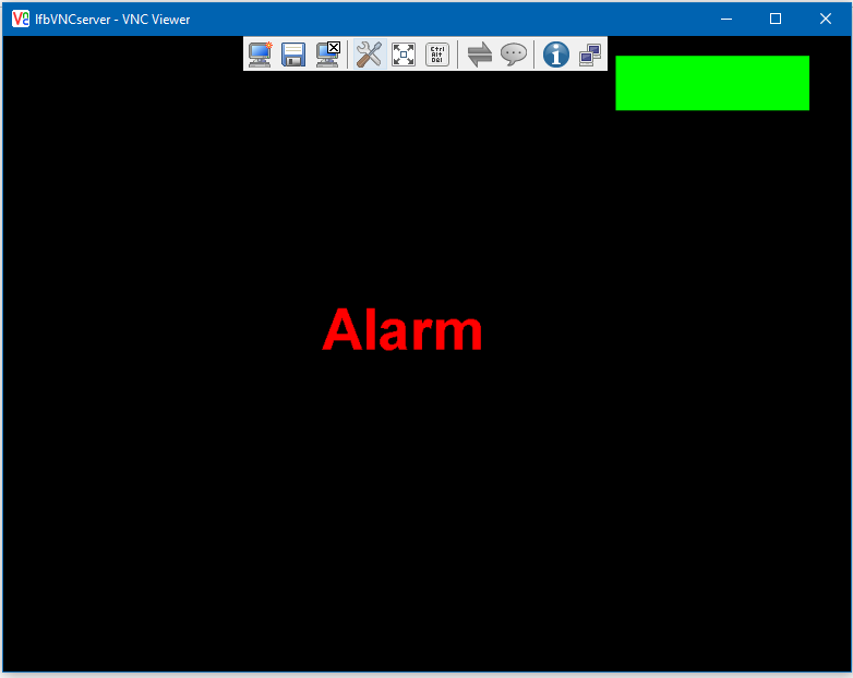
Furthermore the current connection status to the IBM Watson IoT Platform will be shown by an “LED” on the display of a connected monitor.
Green = OK, yellow = disconnected
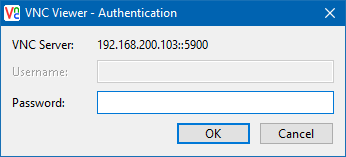
The alarm status should also be shown on the display. The display screen will also be accessible over VNC.
Please note: You need a valid SIM card from a cellphone provider. If you do not have a SIM card, you can also use a normal internet connection for this example. The controller includes a standard RJ45 input.
2 How to start
1. Configuration of the IBM Watson IoT Platform
- Sign up for an IBM Account
- Create Organization and Space
- Create device type
- Create device
2. Configure and program device
- If a SIM card is available, the UMTS module is being configured and tested
- Configure general IoT data of the device in the controller
- Create application
3. Create dashboard in the IBM Watson IoT Platform
- Create new board
- Create new card
3 IBM Watson IoT Platform
If you do not have an IBM Bluemix account yet (corresponds to the IBMid), you will have to create a new account. You can create a test account for 30 days without having to implement your credit card details.
There are numerous ways to start off into the IBM world.
If you use the following link, you can easily go through this documentation step by step.
http://www.ibm.com/internet-of-things/
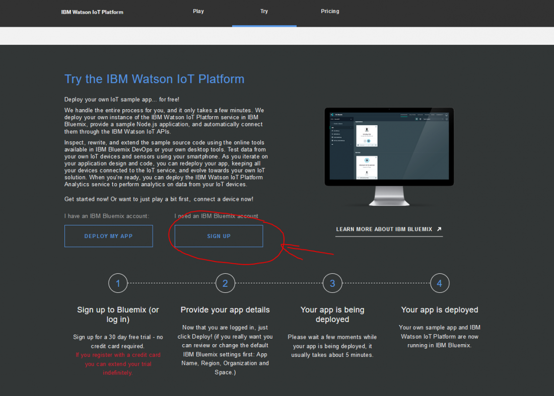
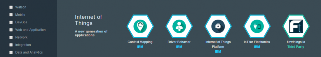
After calling the link, you can see the following or a similar website.
Select: Try IBM Watson Platform (see red circle)

Scroll down until you reach the section Try the IBM Watson IoT Platform.

3.1 Sign up for IBM Bluemix Account (IBMid)
Sign up for an IBM Bluemix account (IBMid) and select the SIGN UP button.
Follow the registration steps
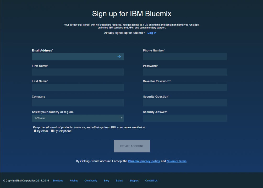
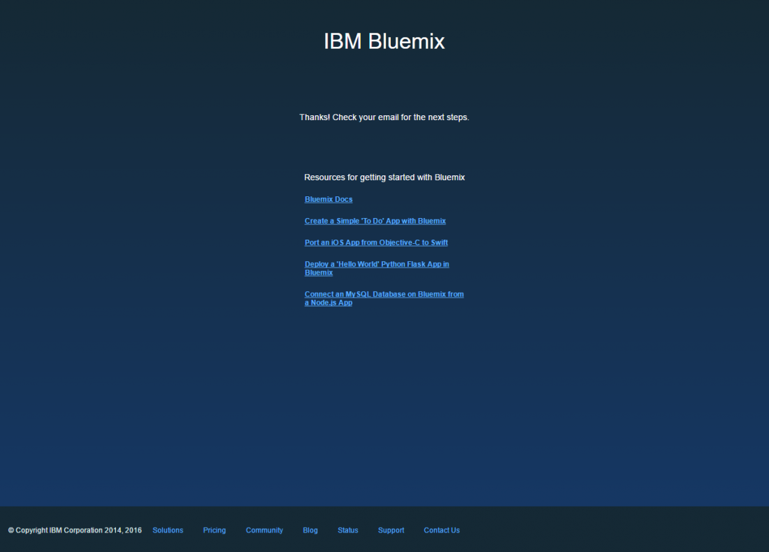
Confirm your account in the email.
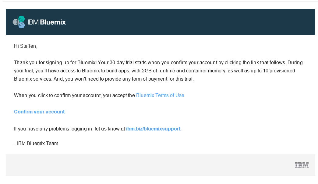

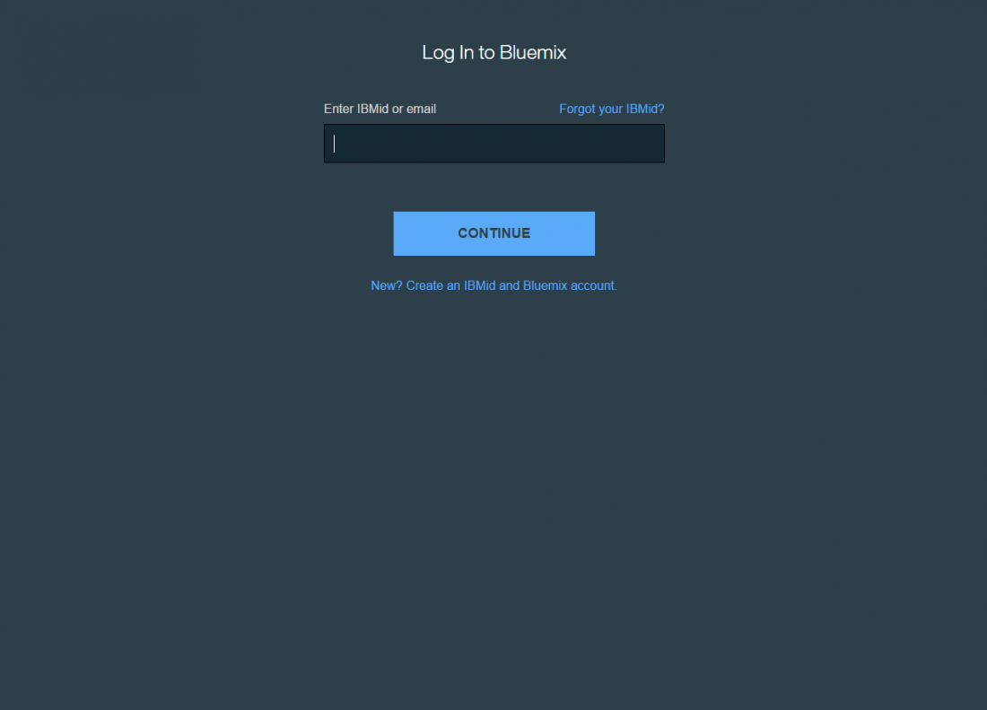
Sign in with your IBMid at IBM Bluemix.
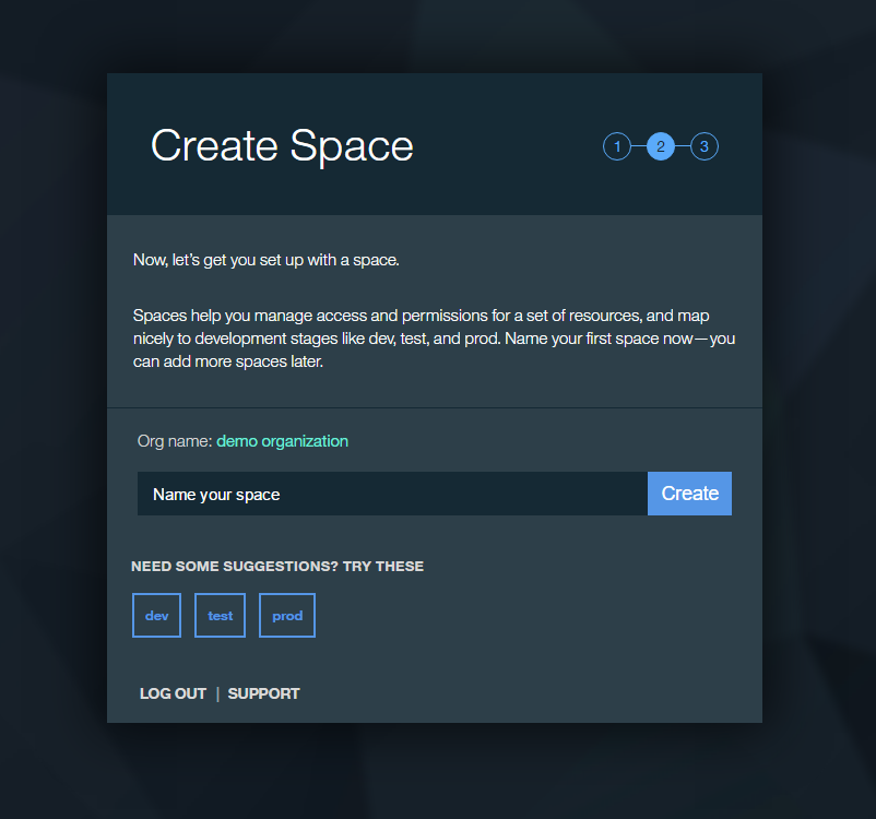
3.2 Create Organization and Space
You will now be asked to automatically create an organization. (Image 10)
In an Organization devices are summarized, which can all be addressed by applications.
You can apply several organizations under your IBMid.

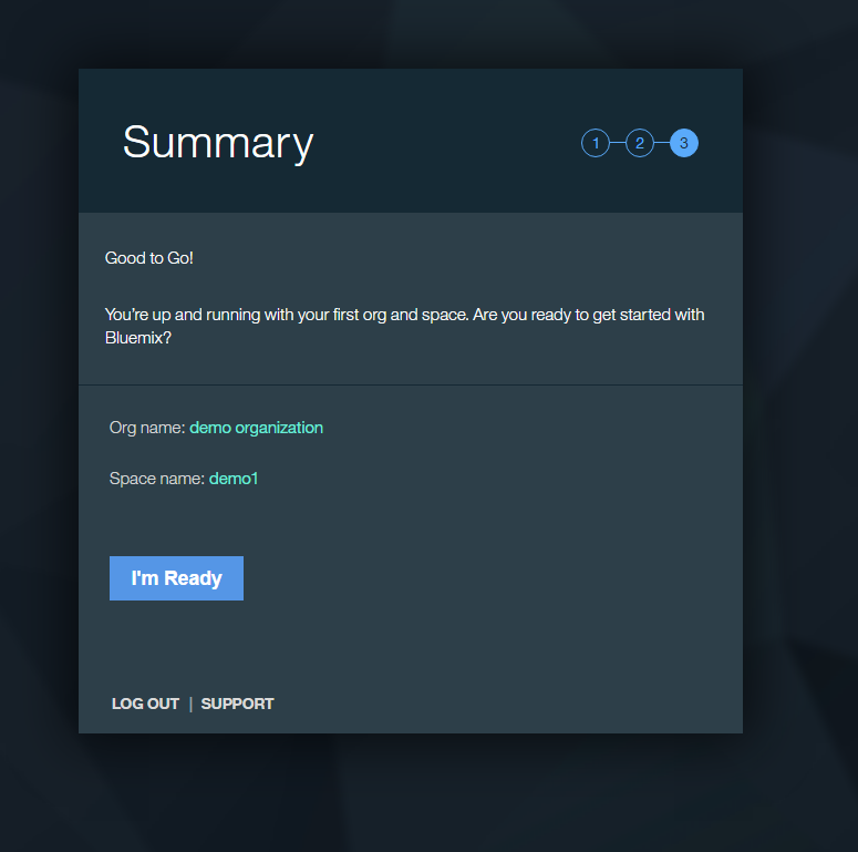
Subsequently, you are automatically asked to create a Space.
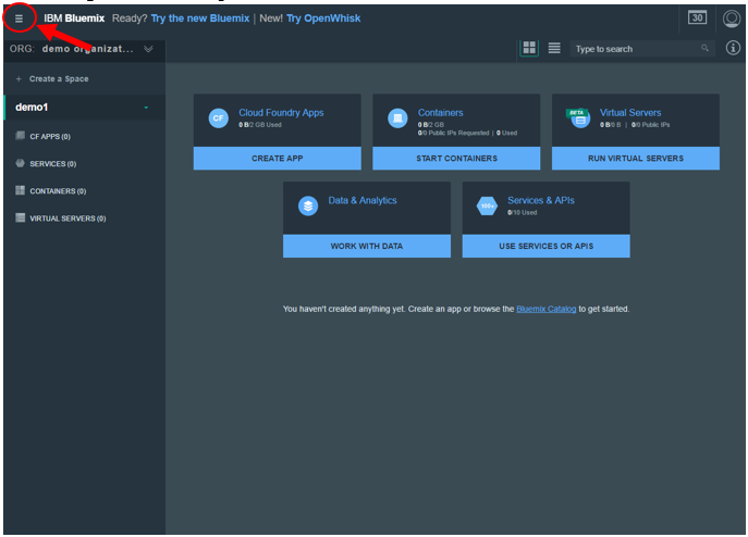
3.3 Bluemix DASHBORAD
You are now directed to the DASHBOARD of your recently created Organization. As you have not yet created any services or platforms in the recently created Space, the dashboard is empty.
Now change to the Catalog over the menu.
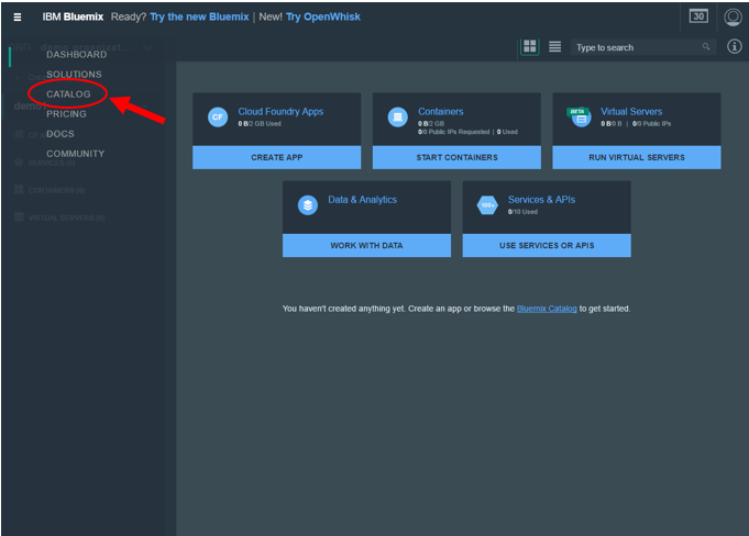
In the catalog you will find a selection of services and platforms.
Now scroll to the section Internet of Things.

3.4 Create an IoT platform
You do not have to implement any more entries. Only press the button CREATE.
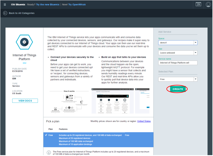
Now start the dashboard for the platform.
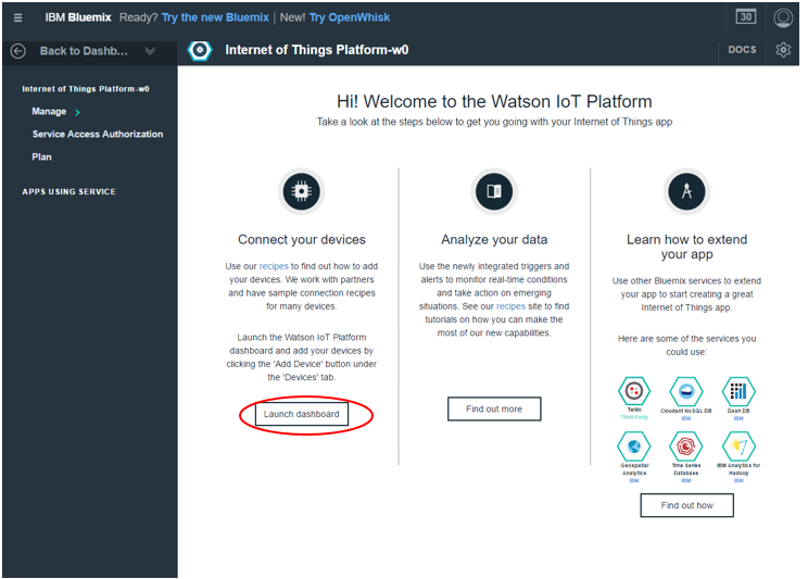
Change to the device section in the dashboard start window.
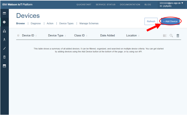
3.5 Add device to the Watson IoT platform
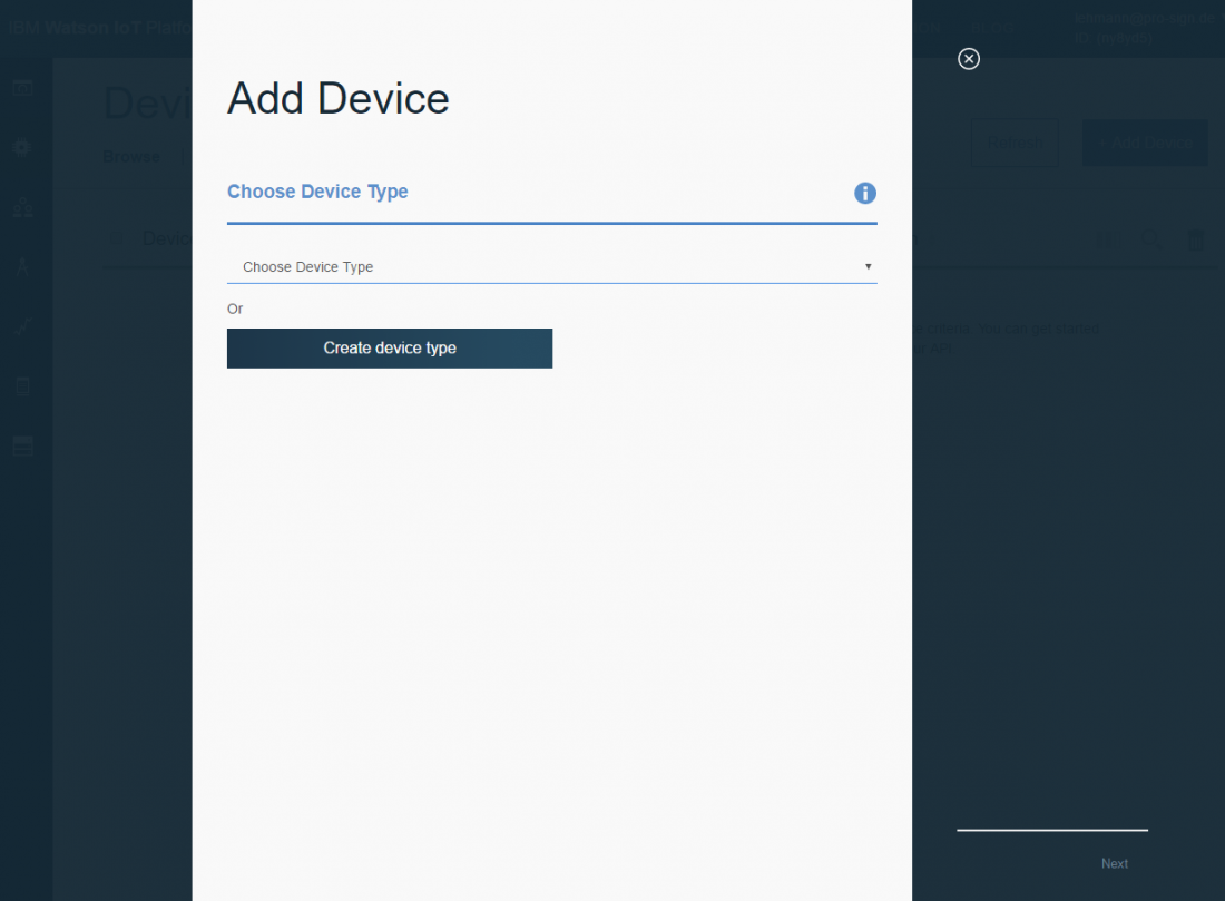
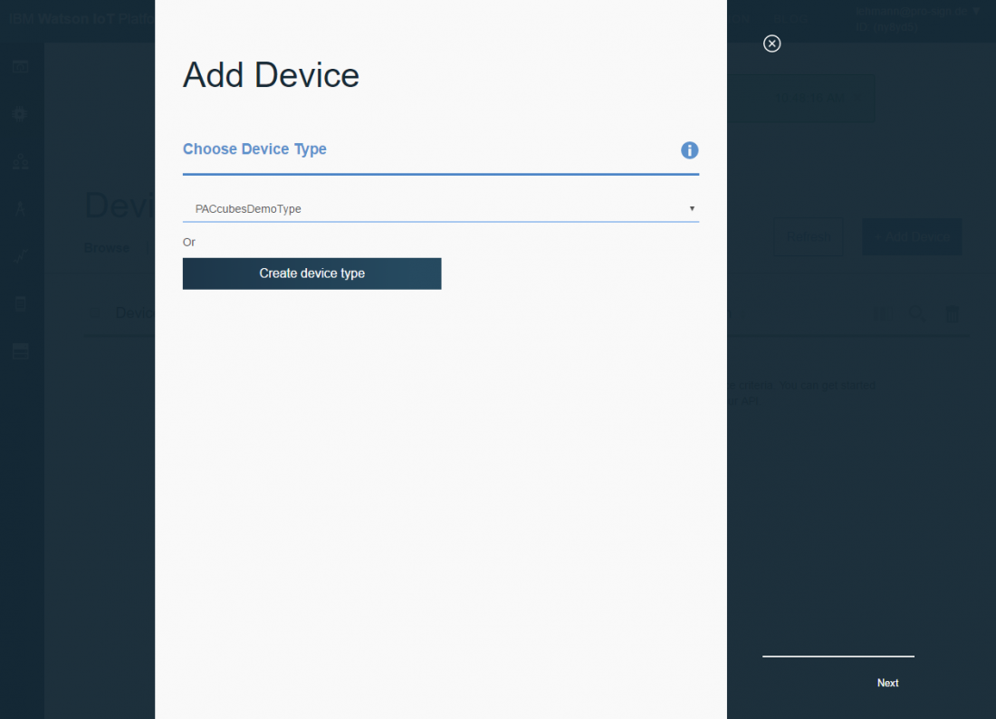
Add a new device.
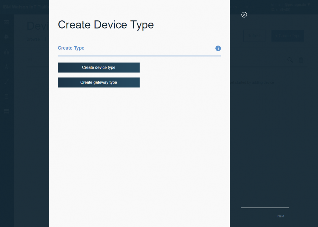
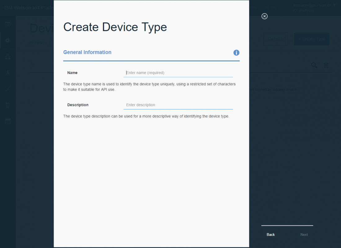
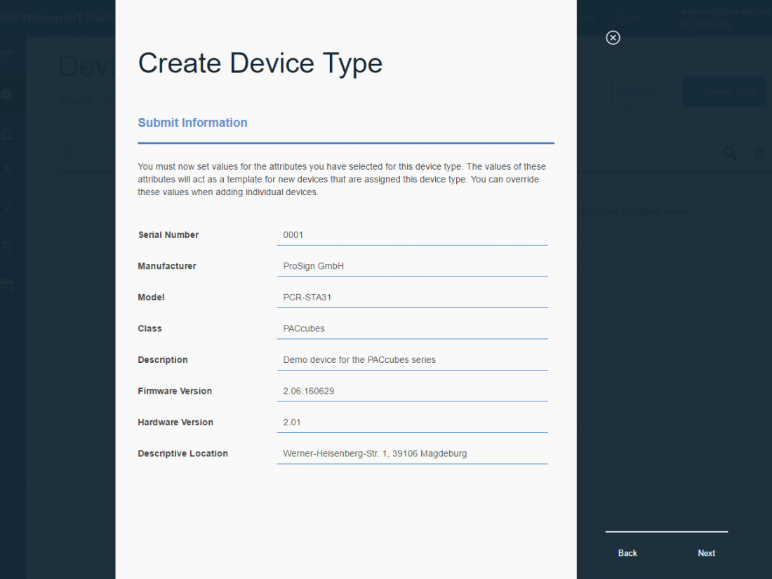
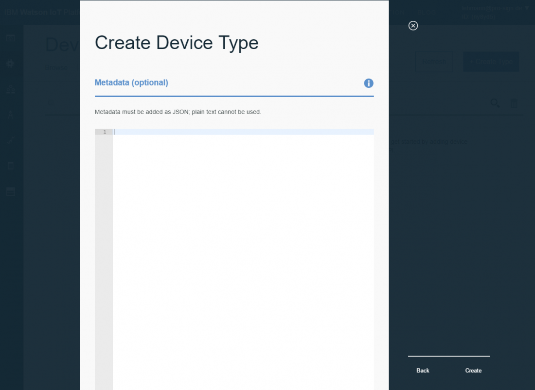
First, create a new device type.
Follow the instructions. You can leave the most fields empty.
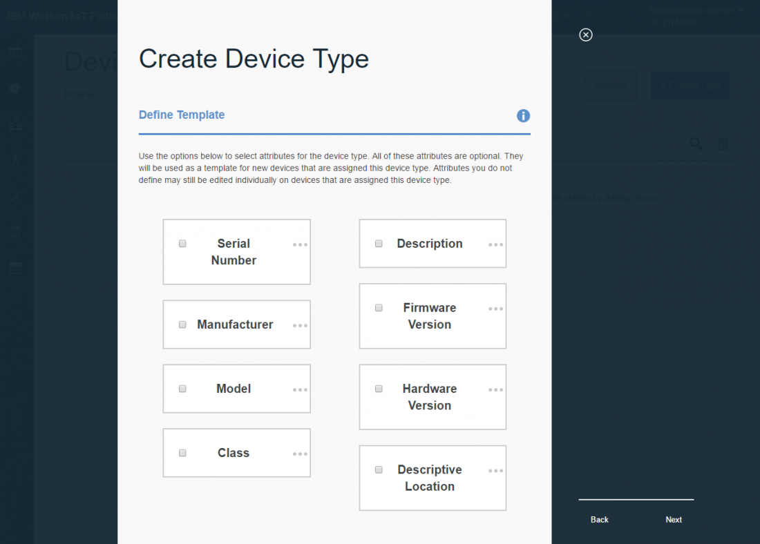
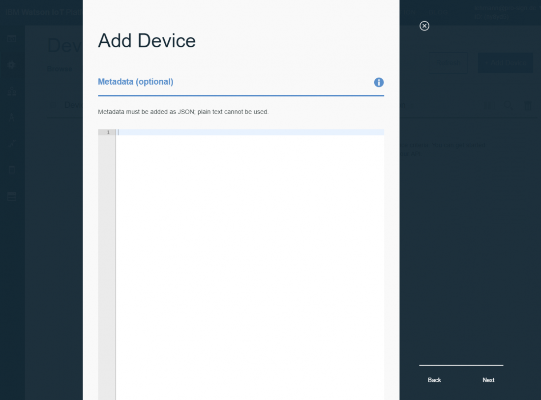
After you created a device type, a new device has to be added.
Follow the instructions of the dashboard.
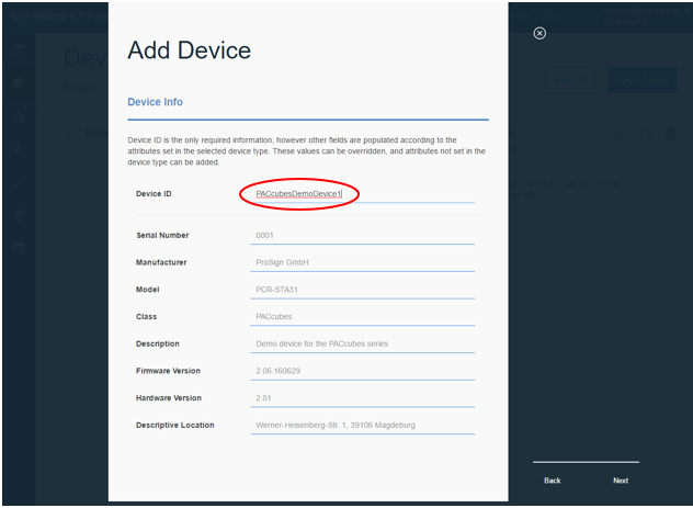
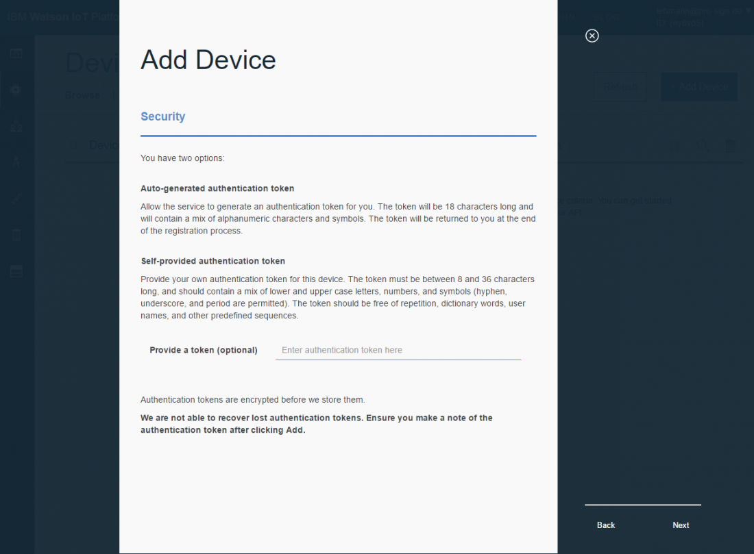

3.6 Save login data of the device
IMPORTANT: In this window, the login data of the device is shown. It is necessary to write down these information, because they will not be shown again. The authentication token is very important here. This token is viewed like the password of the device to enter the Watson IoT platform.
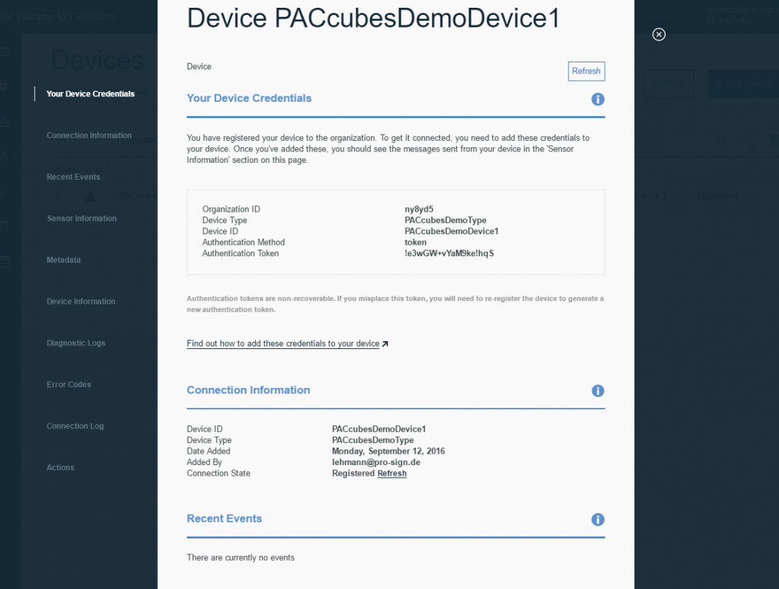
You have now created a device in the IBM Watson IoT platform. No real device, which sends data to the platform exists, yet. The next steps will explain how to prepare the device and how to program an application for this device.
4 Configure PACcubes
After you have created an IBM Blumix Account (IBMid), an Organization and a new Device on the IBM Watson IoT platform, you can configure and program the controller to send data to the IoT platform or receive commands and parameters from the IoT platform.
The delivery condition of the PACcubes device does not automatically come with IoT services. To make them accessible, some device configurations have to be made.
For users who do not frequently work with a Linux system:
The device is delivered with some helpful tools, including the “Midnight Commander”. This tool simplifies the navigation in the Linux system, especially editing and copying of files. To open the Midnight Commander, type in “mc” in the console. The following documentation partly uses this tool for visualization.
Currently device configurations can only be made directly on the device. The following steps or actions are necessary:
1. Connect the controller (f. e. with „Putty“)
- Also see How to change the name of a controller with "Putty"
- If the controller is connected to the office network, and the controller has access to a DHCP server, the controller gets assigned an IP address by the DHCP server. Use the scan mechanism of PACstudio (Connect PACcubes device with PACstudio) to get the IP address.
2. Login with user name and password. (The Demo system is delivered with the user name “root” and the password “root”.
Please change the root password after your first login for safety reasons.
3. Stop the running system
- When the device is turned on, all necessary processes are started. To be able to make changes to process-relevant settings, all processes have to be stopped.
Please note: The name of the PAC runtime kernel on the controller is VICK (Virtual iCon-L Controller Kernel). For that reason the process is called “vicksys”.
- Console command: systemctl stop vicksys

4.1 Configure UMTS module
If the device “PACcubes Station” is delivered with a UMTS module, the following services have to be configured to be able to use the mobile phone connection. When using a permanent LAN connection (no mobile communication), please proceed with paragraph Check UMTS service.
4.2 Configuration of mobile connection
Where can I get the necessary information about my cellphone provider?
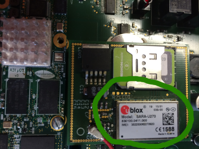
First find out the provider-dependent parameters to dial-up into the cellular network.
To get the exact information please ask your provider.
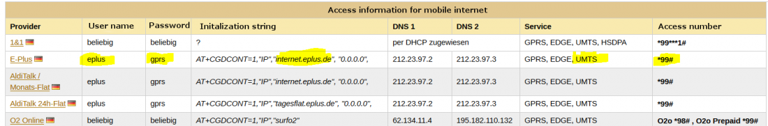
Below you can find the German list of phone providers, or have a look at German provider information here. In our example we are using E-Plus.
For the device PCA-STA31-HN1 only cellphone providers, who offer UMTS service can be used.
The following information are needed for the configuration:
- user name
- password
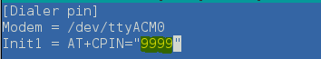
- the marked area of the initialization string
- access number
Enter provider dependent parameters to dial-up into the cellular network
1. Enter the Linux command “cd/home/user1/MobileCfg/” and press enter. With this command you can change to the subdirectory MobileCfg.

2. Enter “mc” in the Linux console, so Midnight Commander opens.
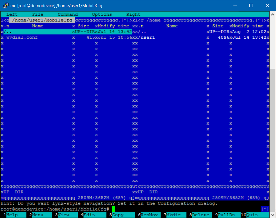
3. Select “wvdial.conf” with the arrow keys.
4. Press the key “F4” (The editor for the file is being called)
5. If the SIM card is secured with a PIN, replace the “9999” with the valid PIN at the marked line (this step can be skipped, if no PIN is needed).
6. Change the following lines in the section [Dialer custom] (the previously defined dial-up parameters of the provider):

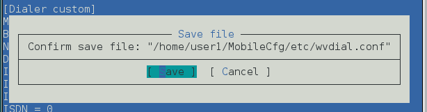
7. When the changes are done, press the button “F2” and select “Save”.
8. Exit editing with the button “F10”
9. Copy the configuration file with the following command: „cp wvdial.conf /etc/“

4.3 Check UMTS service
Check PIN configuration
This step is only necessary if the PIN has been configured
1. Enter the following command in the console: „systemctl start modem-pin“

You might receive the message that calling the service has failed. For the moment you can ignore this message. First request the result (b) to get more detailed information.
2. Request the result (enter command in the console) “journalctl –xn”
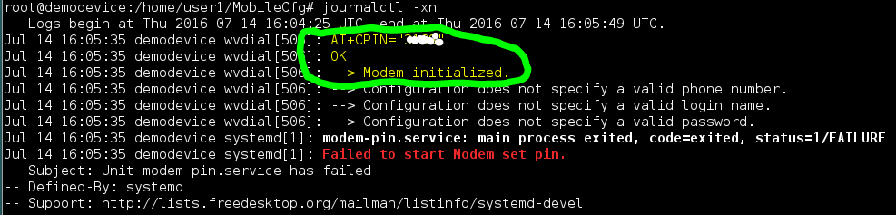
If you see the “OK” in the output information, entering the PIN has been successful (the other errors listed can be ignored at this point).
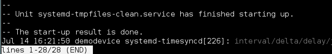
If the command “journalctl –xn” does not reappear in the console, it can be stopped by pressing “CTRL-C”.
If there are more lines available in the journal than displayed, press the “Page up/down button”.
Build-up a connection
1. Enter command in the console “systemctl start modem-connect”

2. Request result, type in „journalctl -xn“
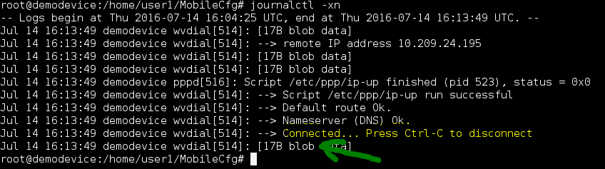
The connection is made. The connection is held and maintained by the „wvdial daemon”. It tries to rebuild a connection, after it has been disconnected.
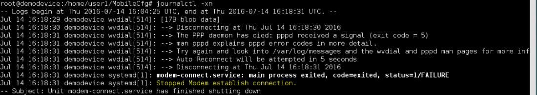
Disconnect
1. Enter command in the console “systemctl stop modem-connect”

2. Request the result, type in “journalctl –xn”
4.4 Configuration to start the necessary service during system start
1. Make sure that you are still in the configuration directory.
Enter the command in the console “pwd”
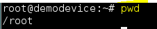
2. If you are not yet in the directory “/home/user1/MobileCfg”, get there by entering the command in the console “cd /home/user1/MobileCfg/”

3. If there was a PIN configuration, the following command has to be executed: „ln -s /etc/systemd/system/modem-pin.service /etc/systemd/system/multi-user.target.wants/modem-pin.service“

With the command “ln”, a linkage is provided
4. Afterwards register the service for the modem initialization with the following command: „ln -s /etc/systemd/system/modem-connect.service /etc/systemd/system/multi-user.target.wants/modem-connect.service“

5. To check if both symbolic links have be created correctly, first enter:
“cd /etc/systemd/system/multi-user.target.wants”
press enter and secondly enter
“mc”
and press enter again.

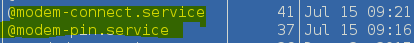
Here you should see either one or both (depending on the PIN request) symbolic link(s).
Symbolic links are marked by an “@” sign.
Further information about “wvdial” and “system”
You can find further information about the mentioned mechanisms and tools (“wvdial” and “system”) on the internet.
https://wiki.archlinux.org/index.php/Wvdial
https://en.wikipedia.org/wiki/Systemd
4.5 Configure IBM Watson IoT platform basic data
Organization, device ID and authentication token are basic data, which are not configured over function blocks. Currently special configuration files have to be changed in the Linux file directory.
Please note: It is very likely, that this will change in future versions. The configuration will then take place over the programming system.
1. To change to the configuration file, enter the command in the console “cd /home/user1/vicksystem”

2. Call the Midnight Commander -> enter “mc” in the Linux console
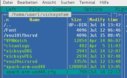
3. Select the file “xpac6-arm-usd40.cfg” with the arrow keys
4. Open the file with the key „F4“ for editing
5. Change the following entries in the section „[IoT]“
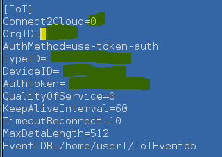
- Connect2Cloud=1
- OrgID=????? (You assigned this when you created the Organization)
- TypeID=????? (You assigned this when you created the device type)
- DeviceID=????? (You assigned this when you created the device)
- AuthToken=????? (You received the authentication token after creating the device)
6. Save with „F2“
7. Exit editor with „F10“
The configuration of your PACcubes Station is finished now. We will now start programming.
Restart the controller
5 Program an application
5.1 Create a project
1. After starting the programming system PACstudio, call the menu Project and the command New
2. Select the template PCA-STA31-HN1.

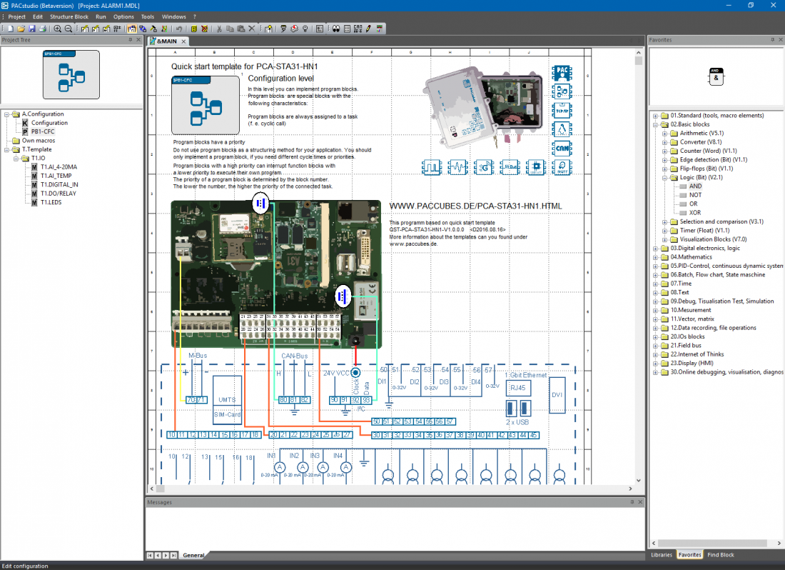
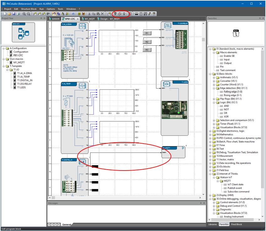
After you have created the project, you can see the first project level, the so-called configuration. On this level, the program blocks are implemented. In our template, one program block has already been implemented. For the most applications this program block is enough. The more program blocks you use, the harder it becomes to control the processes running parallel. (-> learn more about program and macro blocks)
As a little help to start-off, you can see the circuit diagram and the terminal diagram of the controller on the configuration level.
Please note: The circuit diagram only has a documentary character and it is not part of the program, which is downloaded on the controller. The circuit diagram is configured as background image (EMF vector graphic) for the program block (see also: Structure block design).
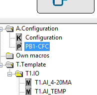
5.2 Program block PB1-CFC
Now navigate to the worksheet of the program block PB1-CFC.
Please note: PB1-CFC stands for program block 1 – Continuous Function Chart (see theoretical background).
1. You will reach the worksheet of the program block by double clicking on the program block in the project tree or
2. Over the context menu of the block in the worksheet in edit mode.
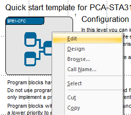
In the selected quick start template, program blocks already contain pre-programmed macro blocks. Macro blocks make it easy to access inputs and outputs of the controller. Macro blocks can be designed individually, you can find an instruction here.

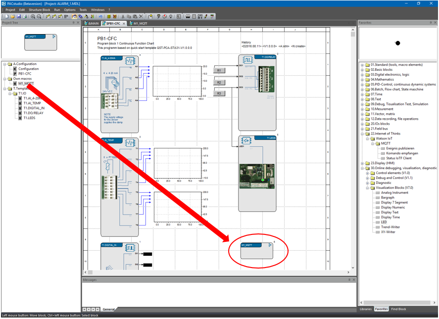
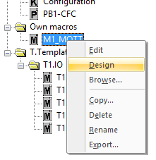
5.3 Create a new macro
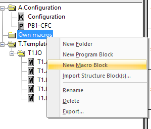
First create a new macro with the name M1_MQTT. For a better overview, the macro will be placed in the prepared folder Own macros.
After you have created the macro, an empty worksheet opens in the workspace to draw the macro functions. You can now implement function blocks.
Check correct connection to the IBM Watson IoT Platform
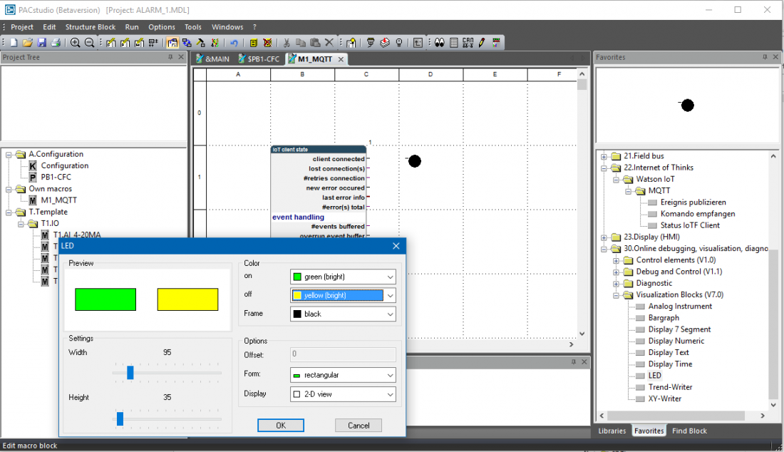
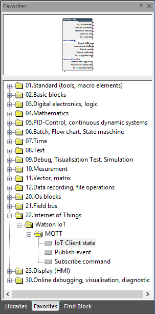
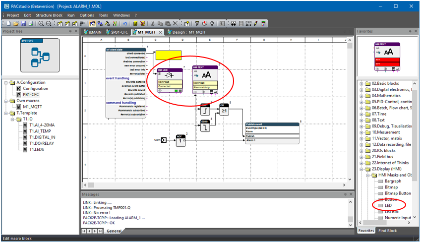
First we will implement a diagnosis block, which signals the correct connection to the IBM Watson IoT Platform. To easily find these blocks, change from Libraries to Favorites on the function block library and search for the library 22.Internet of Things.
Now open the folders Watson IoT, then MQTT and select the block IoT Client. Drag and Drop the function block on the worksheet. After that, implement the block LED form the library 30.Online debugging,.. .
Now connect the output client connected with the input of the LED block.
Now change back to the worksheet of the program block PB1-CFC and implement the new macro block on this worksheet.
5.4 Download the test program on the controller
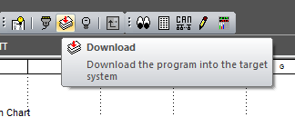
Now select the button Download from the toolbar.
The programming system now changes automatically to the so-called run mode and calls a dialog to login the controller.
Please note: This dialog will only be called, if no controller has been logged in yet (first download).
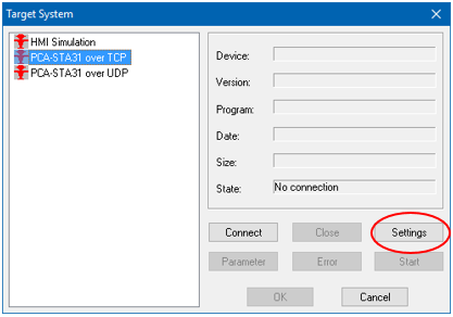
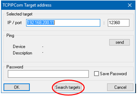
Please select the communication server template PCA-STA31 over TCP. Click on “Settings” and then “Search target”.
Very important: The controller is set to DHCP and will search for a DHCP server in the network. When the controller has found a DHCP server, the controller will use the assigned address. If the controller does not find a DHCP server, the static address 192.168.200.11 is used.
If the computer is in the same IP address range, the search dialog will show your controller. Select the controller and click on OK.
If your controller is not shown immediately or your controller is shown with the address 127.0.0.1, click on the search button again.
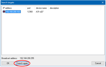
The communication server template PCA-STA31 over TCP will now be configured correctly (IP address and port). When double clicking on the server, the login communication to the controller starts. The programming system now reads a device description file from the controller and shows some information in the dialog.

The programming system will subsequently start the download process and change into online mode after successfully downloading the application.
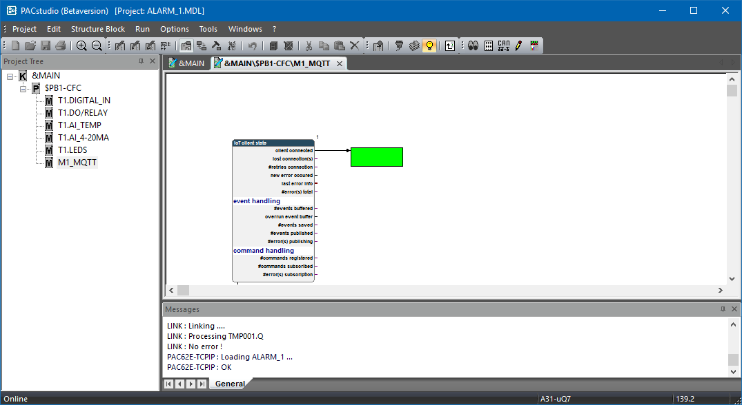
If the LED is green, the connection to the IBM Watson IoT Platform has been successful.
5.5 Send alarm signal to the IBM Watson IoT Platform
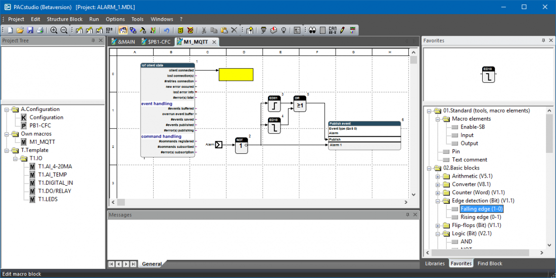
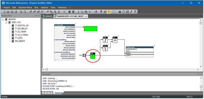
Add another digital input to the macro and implement a NOT block and a block Publish event.
The NOT block is necessary, because the digital inputs of the controller will output a HIGH signal when the contact is open and will only be set to LOW when closing the contact. This logic has to be negated for our task.
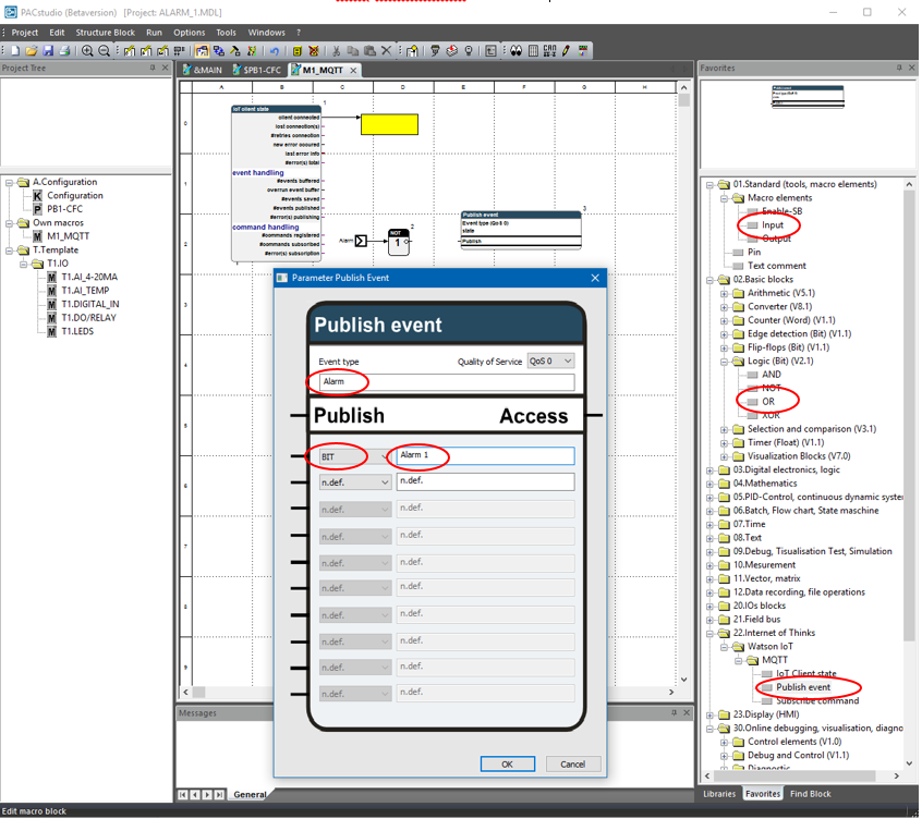
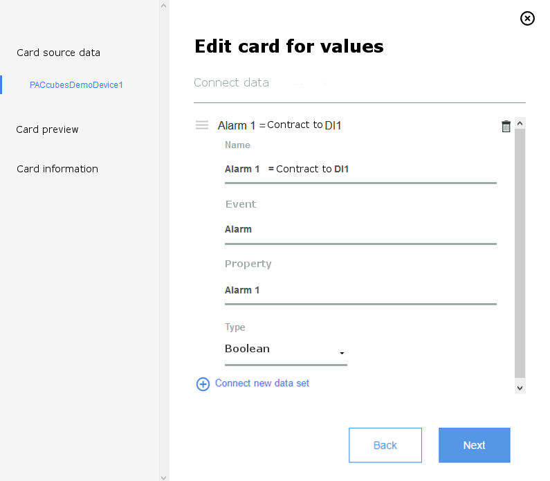
You should configure the block Publish event just like in the image.
- Event type = Alarm
- Event Element 1 = Atam 1 with data type BIT
Now the program has to be extended by giving the Publish event block a signal about when to send. In our case, we always want to send, if the value at the alarm input changes. We will accomplish that by implementing two blocks for Edge detection, which will recognize a falling and/or a rising edge. These signals will then be connected over an OR block.
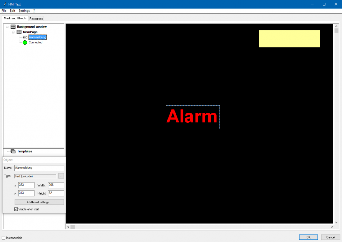
Now we will adjust the design of the macro block and connect the macro input with the DI1 of the controller.
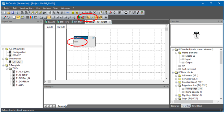
According to the best ability to read the names of the inputs, you can place them to the inside or outside of the macro block by using the button shown in the image.
Now download the program on the controller.
6 Configure dashboard in the IBM Watson IoT Platform
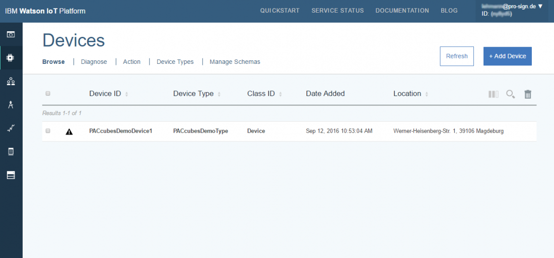
First check if the controller is online.
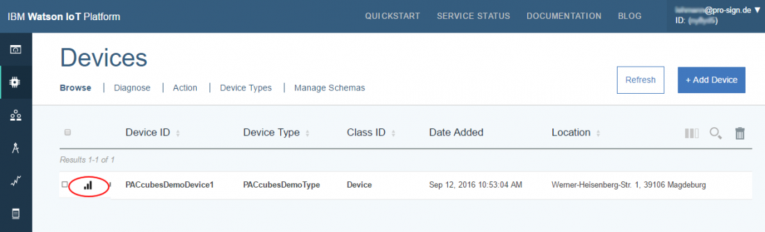
By double clicking on the line with the controller you can call detailed information about the controller.
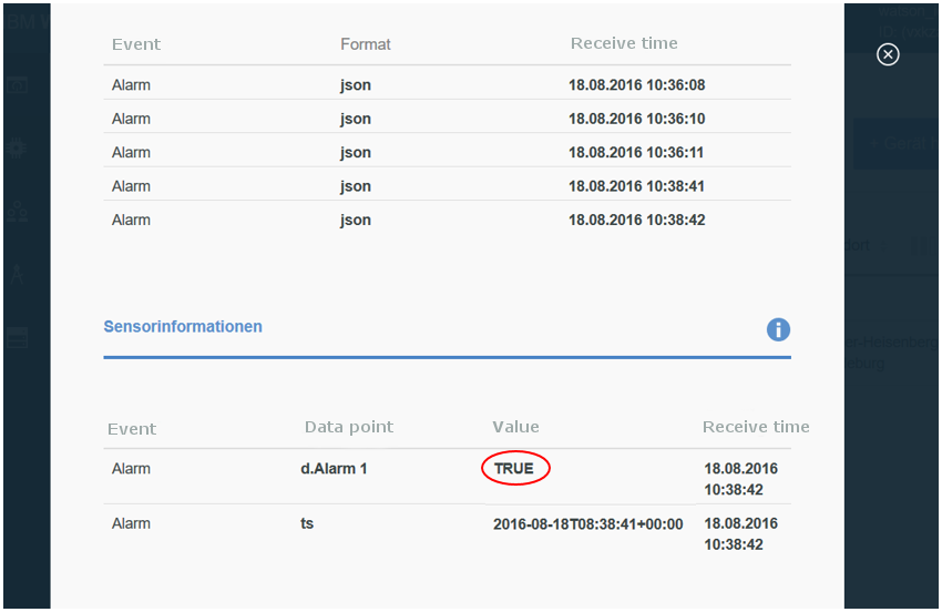
Now you can check if the results have been received.
Change the status of the DI1. The result should immediately be shown (<0.5 s).
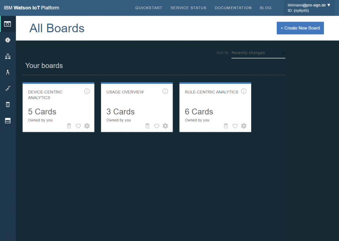
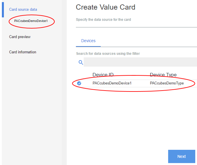
Now change to the board section.
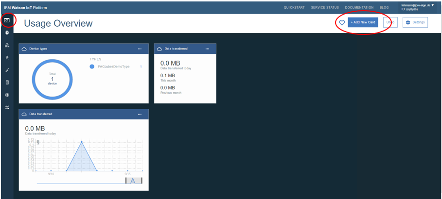
Follow the instructions of the assistant to configure the card.
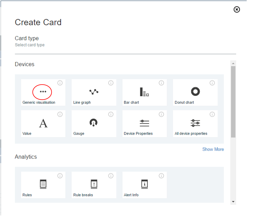
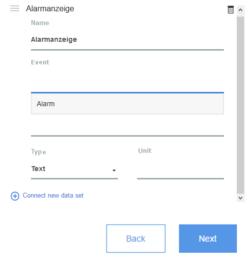
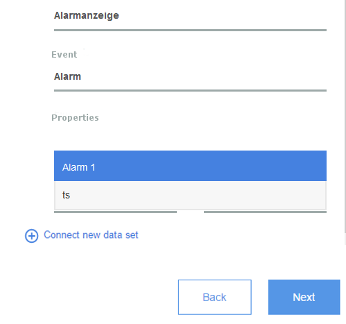
If you click on the empty section Event, the selection of the available events will be shown in a list. Select the event. In our case the event Alarm will show up. In the section Properties you can select the desired value. I our case you can choose between the value Alarm 1 and the time stamp of the event.
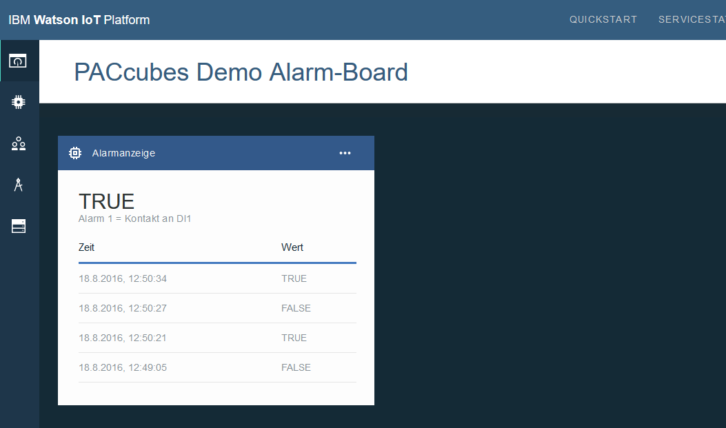
7 Program a display
It might be helpful to see the current status on a display.
The resolution of the PCA-STA31-HN1 is good for 1024*768 pixels.
When implementing HMI blocks, the HMI designer is automatically being called.
If you do not have a monitor connected to the controller, you can also access the screen view over VNC. You can download the VNC client for free on the internet.
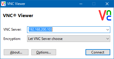
The default password is „master“.