Basics: Programming with blocks
An application program is programmed in a so-called Continuous Function Chart (CFC). But what does that mean really?
By drawing a block diagram, a program is being created. Function blocks are therefore placed on a worksheet and the inputs and outputs are being connected to each other. After such a network made of function blocks and connection lines is drawn, a network description written in a language readable for machines is uploaded on the mini PLC.
The name “Continuous Function Chart” already indicates, that the application program is a network made of blocks and connection lines, running as a continuous process. Just like in an electronic circuit, in which logic gates as f. e. AND and OR are continuously executed, the function blocks in the mini PLC are also continuously called.
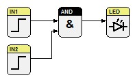
As shown in image 1, the blocks IN1, IN2, AND and LED are constantly called from the PLC. The blocks IN1 and IN2 are continuously reading the current voltage at the digital input terminals 1 and 2, they convert the value into a logic signal (0 or 1) readable for the program. The result for this translation is written on the output as a logic 1 or 0 signal. The value is transferred to the AND block over the connection line. At the AND block, the logic algebra of the AND function is executed and the result of the algebra is written on the output (1 or 0). The connection line transfers the value to the LED block. There, the logic signal 1 or 0 is converted into the corresponding current signal and accordingly, the LED is illuminated or not.
Function blocks (FB)
The function block is the smallest applicable unit of an application program in the PLC-related world. It is the central programming medium in our graphical programming system.
Function blocks can have several output variables and allow the same input values for different output values. That is possible, as it also has internal variables, whose values are preserved even after the block was called.
Function blocks are parametrizable by using input, output and inner variables. Function blocks are always called by program blocks in miCon-L. The call is done by instantiation. The instance is comparable with a copy of the block for a special application case, whereas the necessary memory range is made available. The data is saved between the block calls. This circumstance is commonly called the “memory” of the function block.
In the PLC-related world, functions and function blocks are being distinguished. Here, the function, f. e. an addition, has no memory. However, there is no such distinction in miCon-L. All blocks are called function blocks there.
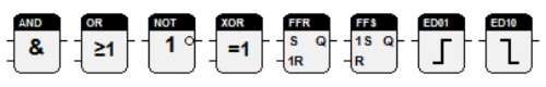
A catalog with all function blocks available for miCon-L you can find under Function blocks.
Continuous Function Chart (CFC)
Translated from the German Wikipedia article: Continuous Function Chart
The Continuous Function Chart (CFC) is a programming language for Programmable Logic Controllers (PLC). Even though it is a language, which is not defined in the IEC 61131-3 standard, it is still an established extension of the IEC programming environment.
Its main field of application is in process control engineering, as complex control and controller tasks occurring in that area can be drawn very well in a CFC.
CFC is a graphical programming language, in which function blocks are connected with each other, instead of implementing a series of textual commands like in classic programming languages. It is following the pattern of circuit diagrams from hardware development. This type of appearance of a program comes in handy for developers of control software, as their technical background is typically in electrical engineering.
CFC can be seen as extension of the function block language, in which no strict line-by-line processing from top left to down right is forced. The function blocks can be positioned freely and the programmer has more possibilities to connect the inputs and outputs.
The function blocks in miCon-L were programmed in the programming language C and are delivered as standard blocks by the manufacturer of the PLC.
Edge Controller
Translated from the German Wikipedia article: Edge Computing
The edge controller is a form of a programmable logic controller, where the processing elements come closer to the sensor. Thereby, the sensor data can be analyzed and filtered much faster. This allows it to reduce the amount of data to be processed in peripheral computer centers. The edge controller differs from the conventional PLC mainly by its greater ability to process data, which is achieved by the usage of multi-core processors with a higher computing power.
PAC Programmable Automation Controller
PAC stands for Programmable Automation Controller, a compact controller, which combines the characteristics of a computer-based controlling system and a Programmable Logic Controller (PLC).
For iCon-L and all deriving programming systems (PACstudio, test.con, miCon-L) the term is used in a wider sense, as iCon-L is also used for smaller controllers. For that reason the term PAC is generally used for all iCon-L runtime systems.